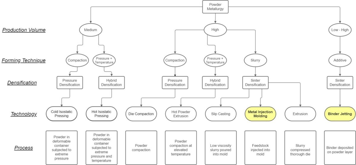
Powder metallurgy, the process of converting fine powders into usable parts through pressure and sintering, has been used in mainstream manufacturing for over a hundred years. Techniques, materials, and processes have all steadily improved as the adoption of the technology has gained significant popularity. The figure below illustrates the range of processes available to modern designers.
Among powder metallurgy techniques, metal injection molding (MIM) distinguishes itself for being one of the most utilized processes. The key advantages being its capability to produce dimensionally accurate intricate and net-shaped parts at high volumes, all while maintaining mechanical properties equivalent to wrought materials.
However, the advent of other technologies, such as computing and inkjet printing, has brought powder metallurgy into the 21st century with the introduction of additive manufacturing. Although additive manufacturing has undeniably revolutionized the manufacturing landscape, traditional methods continue to hold significance. Factors such as cost, complexity, quality, and production volume must be carefully weighed when selecting the most suitable technology.
This article aims to draw comparisons between metal injection molding and metal binder jetting, examining their respective merits while keeping in mind these critical considerations.
Understanding Binder Jetting Additive Manufacturing and Metal Injection Molding
Metal injection molding (MIM) is a molding and sintering process that produces intricate parts from a mixture of metal powder and a binder slurry. The process involves mixing metal powders with a polymer binder and additional additives to create a feedstock. This slurry-like feedstock is then injected into a molding machine at high pressure to form the desired shape. After molding, the component is ejected from the mold and subjected to a thermal or solvent-based debinding process, eliminating the binder and resulting in a porous metal structure. The debound parts undergo sintering in a furnace at a temperature close to the metal’s melting point, resulting in a fully dense metal part. Secondary operations, such as machining or heat treatment, may be employed to achieve the desired properties.
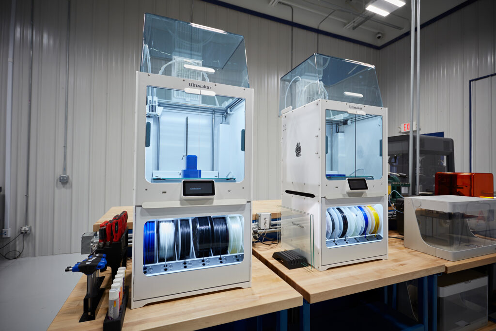
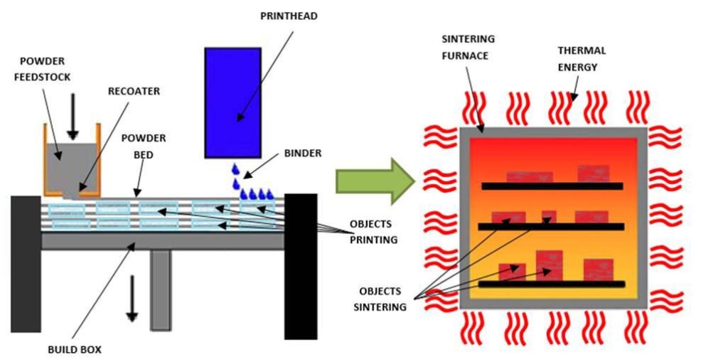
Metal binder jetting (MBJ) is a sinter-based method of 3D printing that produces highly detailed parts from powdered feedstock. Fine metal powder is evenly dispensed across a build box, maintaining a precise thickness. An inkjet print head travels across the powder layer, selectively applying a liquid binding agent, akin to glue, onto the powder layer, defining the cross section of the intended part. This sequence repeats until the part reaches its full height. Subsequently, the build box is removed, and the freshly printed components are delicately excavated, staged, and sintered. The sintering process occurs in an industrial furnace, subjecting the parts to temperatures near their melting points, thus solidifying the structure to full density. Secondary operations, such as machining or heat treating may be applied to attain the desired properties.
While both MIM and MBJ are powder metallurgy processes capable of producing final metal parts, each possesses distinct advantages and limitations. Factors such as cost, complexity, quality, and production volume play a pivotal role in determining the most suitable process for a given application.
Design Considerations
Due to its nature as a molding process, MIM is bound by the limitations imposed by mold designs. These constraints encompass considerations such as parting lines, imprints from ejector pins, cavities, draft angles, and other molding-related factors. Additionally, the design of the part must account for its ability to endure the molding process, necessitating a stable backbone and sufficient stiffness to withstand the ejection from the mold.
Given the requirement for lead time and upfront costs associated with mold production, MIM is not an optimal choice for prototyping. However, simulation software is available to model and simulate both the MIM and sintering processes, providing a means to verify that the final part will meet the desired specifications before actual production begins.
Wall thickness can range from a minimum of 0.1mm to a maximum of 50mm, provided it remains constant across the entire part. The minimum feature size, including holes, pins, and stiffeners, is 0.1mm. The complexity of MIM parts is limited to line-of-sight features, and internal or interlocking features are not feasible. Optimal mass for a MIM part typically falls within the range of 0.01 to 50 grams. While optimal dimensions are approximately 50x50x50mm, it’s crucial to evaluate each design individually for suitability.
| PARAMETER | METAL INJECTION MOLDING | METAL BINDER JETTING |
| Shaping requirement | Consider mold design: parting lines, cavities, ejectors, runner, draft… | Design Freedom (No mold) |
| Sintering requirement | Part must have a stable backbone structure* | Part must have a stable backbone structure* |
| Sinter setters / supports | (when required) machined in ceramics, do not shrink with part. | (when required) can be printer, setter shrinks together with part |
| Wall thickness | min 0.1mm, max 50mm.Must be constant across part. | min 0.2mm, max 50mm.Can vary across part. |
| Design aids | Moldflow simulation software | Rapid design iteration 10-15 days, Sinter simulation software |
| Minimum feature(hole, pin, cavity, beam…) | 0.1 mm | 0.2 mm |
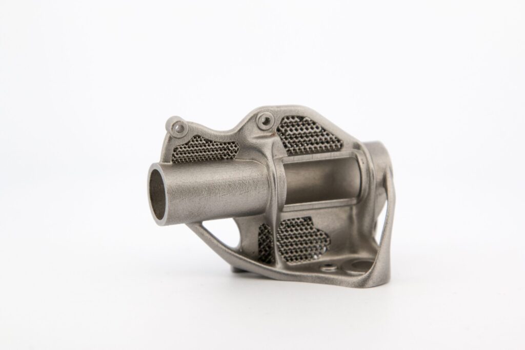
| Complexity | Only line-of-sight features | Intricate internal features are possible |
| Interlocking features | Not possible | Possible, minimum 0.2mm clearance. |
| Optimal Mass | 0.01 – 50 g | 0.1 – 200 g |
| Optimal Dimensions | Min: 0.5 x 0.5 x 0.5 mmMax: 50 x 50 x 50 mm | Min: 1 x 1 x 3 mmMax: 80 x 80 x 55 mm |
Quality Considerations
MBJ and MIM adhere to common material standards, including MPIF 35, ASTM B883, and ISO 22068. Similarly, they are subject to equivalent production quality and testing standards. Both processes result in isotropic mechanical properties, achieving a density range of 96-98%.
Prior to any post-processing, MIM typically yields a surface finish of 1.2µm. However, surface features such as parting lines, ejection marks, and runners may be noticeable. Achieving a dimensional resolution of 100µm is feasible. Under typical conditions, MIM parts can achieve a tolerance of +/- 1.6%, with the potential for improvement to +/- 0.9% following optimization.
Typical as-printed surface finish for MBJ is 4um. Although there are no surface artifacts from a mold, print lines are observable and become more pronounced near horizontal angles. A dimensional resolution of 35um is attainable. Under typical conditions, MBJ parts can achieve a tolerance of +/- 1.7%, with potential for +/- 0.5% after optimization.
| PARAMETER | METAL INJECTION MOLDING | METAL BINDER JETTING | |
| Mechanical Properties | Per industry standards | Per industry standards | |
| Chemical Properties | Per industry standards | Per industry standards | |
| Metallurgical Microstructure | Isotropic,96%-98% densification | Isotropic,96%-98% densification | |
| Typical Surface Finish | 1.2um | 4um | |
| Surface Features | Parting lines, Ejectors, Runners (>80um) | Print Lines (<35um) | |
| Resolution | 100um | 35um | |
| Dimensional Tolerance*1, 2, 3, 4 | Best practice conditions | ± 0.9 % of dimension | ± 0.5% of dimension |
| Typical conditions | ± 1.6 % of dimension | ± 1.7% of dimension | |
- Extremely design dependent
- Example considering ~25 mm dimension
- MIM data source: EPMA 2018 MIM Brochure
- MBJ data source: Azoth internal production records
Cost Considerations
MBJ presents several cost advantages over MIM. The absence of a mold requirement allows for high customization with no additional cost, enabling multiple designs within the same print. Serialization with different numbers on each part is feasible. Prototypes do not incur the cost and lead time associated with creating a new mold. Additionally, parts can be easily rescaled to enhance dimensional accuracy without the expense for mold changes. Furthermore, there is no requirement for mold maintenance or storage in the MBJ process.
In comparison to other additive manufacturing technologies, MBJ is more capable of high-quality production. However, MIM often proves more cost effective at high-volume production. Molds can be designed to form multiple parts in a single shot, and the injection process is significantly faster than the printing process. In most cost comparisons, there is a breaking point at a certain volume where MIM is more cost effective than MBJ.
Choosing Between MBJ and MIM
It is important to carefully consider the specific project requirements before choosing between MIM and MBJ. While both processes produce comparable parts, each has distinct advantages and limitations.
MIM, with its molding and sintering approach offers intricate part production but is constrained by mold design limitations. It excels in high-volume production of reasonable complex parts. However, MIM may not be the ideal choice for prototyping, mass customization, or extremely complex geometries.
On the other hand, MBJ layer-by-layer process eliminates the need for molds, providing flexibility for extremely complex designs. It is well suited for high-quality parts where customization and serialization are essential. However, its cost effectiveness diminishes in comparison to MIM at high-volume production.
When ready, submit your parts to Azoth for review. Still have questions? Reach out to our application engineering team at info@azoth3D.com with any questions.