“Perfection is achieved, not when there is nothing more to add, but when there is nothing left to take away.” -Antoine de Saint-Exupéry, French writer and aviator
Design and manufacturing are inextricably linked. The brilliance of a design is rendered useless if it lacks feasibility in manufacturing. A skilled designer consistently considers the practical aspects of production. Can I use a standard shape or extrusion? How will this be fixtured? What tooling will be needed? Etcetera, etcetera. These considerations bridge creativity and pragmatism to make a design that aligns with the realities of manufacturing.
The process used to make a part defines the boundaries of its design. Limitations exist for material removal, complexity of geometry, tooling, setup and fixturing, multi-step processing, and more. All of which impact design flexibility, efficiency, and cost.
Additive manufacturing charts a new path for producing parts. Although subject to its own unique set of limitations, the boundaries of design grow broader. This newfound freedom poses a challenge for designers—to not only consider what they can add but also what they can strategically remove.
In traditional manufacturing, where material is often retained for expediency or simplicity, such excess can pose challenges when transitioning to additive manufacturing. This article discusses the significance of eliminating surplus material in the context of metal binder jetting and provides guidance for designing streamlined and efficient parts.
Why trim the fat?
In machining, the starting point is always an oversized part, whether it’s a billet, casting, or forging. The final geometry is achieved by progressively removing material through incremental cuts. Particularly with hard metals, each cut takes time, leading to an increase in costs. When the weight of the part is not a critical factor, the removal of excess material is not justified, and the surplus material remains.
Frequently, designers find it more convenient to begin with standard shapes, such as common extrusions or angles. While these starting shapes may not perfectly align with the intended part, they represent an economical choice. Likewise, the resulting part retains more material than the application warrants.
Alternatively, the metal binder jetting (MBJ) process incrementally adds material, layer by layer. Unlike a CNC machine, where machining time correlates with the intricacy of details, in MBJ 3D printing, the printing duration is solely determined by the part’s height. Retaining large volumes of material in metal binder jetting does not result in time or cost savings; instead, it has the opposite effect. To put it simply – less powder, less binder, less cost. Designers must reassess their approach, recognizing that volume that does not contribute to the part’s application raises production expenses.
Beyond material costs, several other factors influence the overall success of a metal binder jet part. Metal binder jetting is a sinter-based process. To account for shrinkage during sintering, printed parts are initially oversized. However, thick and bulky sections may encounter significant thermal stresses, leading to cracks in the final part. In some cases, rendering the design impractical for metal binder jetting.
Preceding the sintering phase, the entire build undergoes a cycle in an oven to cure the binder. This curing process hardens the binder, ensuring the parts can withstand the subsequent depowdering stage. The duration of the curing process is determined by the amount of binder consumed during printing. By minimizing unnecessary material, the binder consumption decreases, leading to reduced curing time and accelerated overall production.
In metal binder jetting, retaining excess material results in heightened costs, an elevated risk of cracking during sintering, and prolonged curing and debinding times. These considerations collectively emphasize the importance of designs that are efficient and streamlined.
Design Process for Streamlined Parts
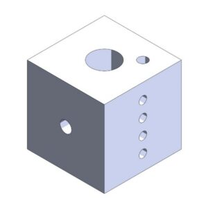
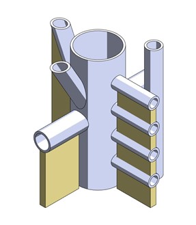
Let’s explore the case of a hydraulic manifold and the process of transitioning from a design tailored for traditional manufacturing to one optimized for metal binder jetting.
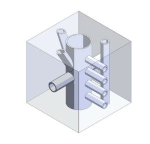
- Trim the part down to the features that are functional.
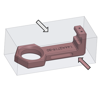
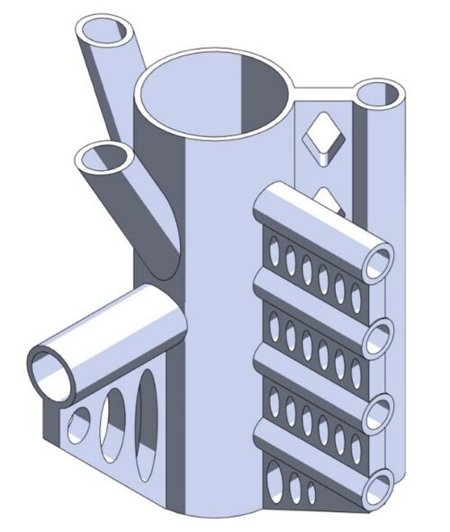
Hydraulic manifolds are commonly made from large metal blocks with holes drilled in from various directions. Besides the walls of the interior channels, the remainder of the block serves no purpose. In this example, a simple shell command is employed. This common computer aided design (CAD) command removes the bulk of the material, leaving a specified wall thickness to the channels.
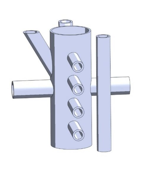
- Trim the part down to the features that are functional.
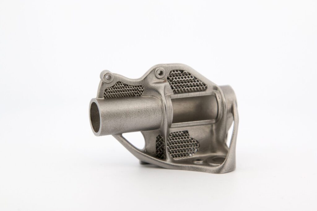
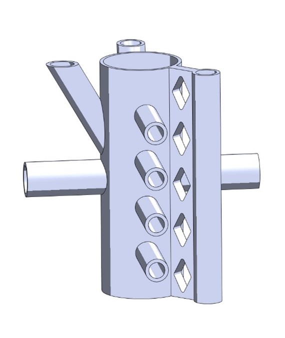
After applying the shell command to the manifold, one channel became disconnected from the rest. To address this, a connecting wall was strategically added, integrating the previously isolated channel into the overall structure, resulting in a unified and cohesive part. Diamond shaped holes were cut into the wall to further lightweight and save on material.
- Consider printing and sintering orientation.
While metal binder jetting doesn’t have the same support requirements as other metal additive manufacturing processes, a form of support remains essential to prevent parts from succumbing to gravity during the sintering process. In this context, the supporting structure is referred to as a ‘setter,’ and it is typically necessary to uphold any substantial overhanging features. Our manifold is orientated in a fashion that minimizes the overhangs.
- Considering additional features to minimize overhangs.
Eliminating the need for a setter in specific features can be achieved by introducing walls underneath overhangs. These supplementary walls can be designed with a chamfered angle of 45 degrees and incorporate elliptical holes strategically placed to minimize material usage.
- Fillet or chamfer everything.
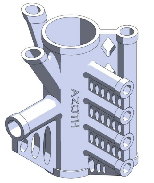
Sharp angles can serve as stress concentrators in the sintering process. Incorporating fillets or chamfers along all edges enhances the distribution of thermal and mechanical loads, thereby reducing the risk of cracking.
In this instance, the advantages of metal binder jetting are further demonstrated by the incorporation of a logo onto the manifold. Metal binder jetting offers the flexibility to include logos, part numbers, dates, or any other text on the part with minimal to no additional cost.
From Thick to Thin…
In conventional manufacturing, where material is commonly left for the sake of expediency or simplicity, such excess can present hurdles when shifting to metal binder jetting. This excess material leads to increased costs, a higher likelihood of cracking during sintering, and prolonged curing and debinding times. Fortunately, this article offers guidance on removing bulk and unnecessary material to optimize for the metal binder jetting process.
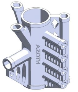
Through the identification of functional features, the consolidation of all components, thoughtful consideration of sintering orientation, minimization of overhangs, and the incorporation of fillets and chamfers, the resultant part is streamlined and well-prepared for the metal binder jetting printing process.
Original Design
Optimized Design
| Volume: | 870.58 cm3 | 49.66 cm3 |
| Weight: | 6,790.52 g | 387.32 g |
| Reduction: | – | 94.3% |
If you have questions or want to explore further, feel free to reach out to our Application Engineers at info@azoth3d.com. When ready, submit your parts to Azoth to make your part a reality.