Design Guidelines

1

Preparing Your File

Accepted file types: .sldprt, .f3d, .step, .stp, .stl

All of Azoth's manufacturing processes start with a digital model. Native files from SolidWorks (.SLDPRT) and Autodesk Fusion 360 (.F3D) are best so that no details get lost in translation. Likewise, a STEP file is a universal format compatible with all CAD software and is ideal to submit (.STP or .STEP).

If CAD files are not available, an STL file is accepted across all additive manufacturing. An STL is a tessellated model that approximates the original design. Too low a resolution will look faceted and jagged; too high won't increase quality and makes the file size unwieldy.
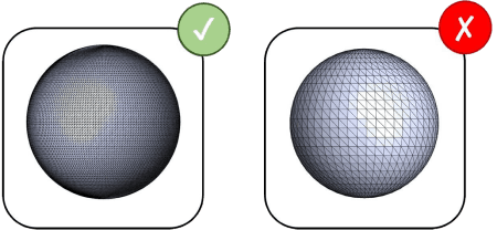

STL resolution comparison — a smooth high-resolution sphere versus a faceted low-resolution sphere
2

Ideal Part Size

Small and complex parts are Azoth's specialty. As a rule of thumb, 5mm to 75mm is optimal (about the size of your fist or smaller). We recommend not exceeding 150mm in the longest dimension—though larger components are considered case by case.

Ideal Part Size diagram
3

Minimum Wall Thickness

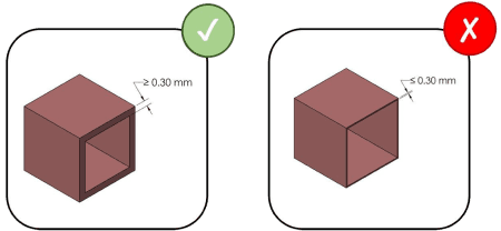
Minimum wall thickness should be no less than 0.30mm on any cross-section of any part feature. This also applies to minimum distances between walls. Requirements may vary depending on size and feature shape.

Minimum Wall Thickness diagram
4

Hole Size & Internal Channels

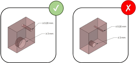
The minimum hole size achievable is 0.20mm in diameter. Inaccessible internal channels should be no less than 3mm in diameter. These values depend on depth, surrounding geometry, and accessibility of the feature.

Hole Size & Internal Channels diagram
5

Edges & Corners

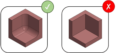
Sharp edges are prone to chipping prior to sintering and likely to propagate cracks. Adding fillets and chamfers to all sharp edges and corners minimizes risk without adding any additional cost or lead time.

Edges & Corners diagram
6

Aspect Ratio

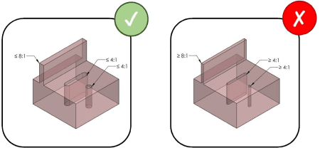
An aspect ratio is the proportion of a feature's dimensions—the larger one dimension is versus another, the larger the aspect ratio. The maximum recommended ratio depends on the feature type:

  • Height-to-Wall Thickness≤ 8:1
  • Slot Depth-to-Width (< 2mm width)≤ 4:1
  • Slot Depth-to-Width (> 2mm width)≤ 8:1
  • Hole Depth-to-Diameter (< 2mm dia.)4:1
  • Hole Depth-to-Diameter (> 2mm dia.)8:1

Features exceeding the recommended ratio are likely to fail—more prone to fracture, hard to depowder, and susceptible to warping during sintering. Enclosed walls, supports, gussets, and ribs can minimize risk.

Aspect Ratio diagram
7

Text & Surface Texture

Part numbers, logos, and patterns can be easily implemented at no additional cost. Surface textures can also be added for a unique look or improved functionality.

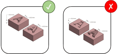
Debossed text:spacing at least 0.3mm apart at all cross-sections, embedded a minimum of 0.4mm for legibility. Letters with free-standing posts (e.g. “A”) must follow the 8:1 aspect-ratio criterion.

Embossed text: spacing at least 0.3mm apart at all cross-sections, following the 8:1 design ratio for lettering height.

Best fonts: Arial Rounded MT Bold, Arial Black, Calibri.

Text & Surface Texture diagram
8

Exit Holes

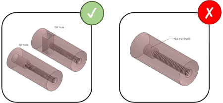
Exit holes provide an opening for excess powder to escape during depowdering. Without them, interior channels can only reach so deep before powder removal becomes challenging—risking craters on walls, eroded threads, and rounded corners.

Exit Holes diagram

Still Have Questions?

Contact us today and our Applications Engineering team will get back to you as soon as possible.